Difference between revisions of "Making New Models & Textures"
m (→Creating a 3D model) |
m (→UV Mapping the model) |
||
| Line 100: | Line 100: | ||
''Note: there are other methods for applying textures to models, but this guide only covers UV mapping.'' | ''Note: there are other methods for applying textures to models, but this guide only covers UV mapping.'' | ||
| − | + | 1. Select the entire object, and at the bottom of the drop-down menu choose ''UV Mapping -> Direct''. A new window with the object will pop up with a title of ''AutoUV Segmenting:'' and the name of your object: | |
| − | |||
| − | + | [[Image:OG_Tuto_CustomModel_UV_1.png]] | |
| − | |||
Now we have to Divide the object into different shapes so that it can unfold it properly, just like in the globe example. | Now we have to Divide the object into different shapes so that it can unfold it properly, just like in the globe example. | ||
| Line 110: | Line 108: | ||
You can separate different pieces either by marking which edges to cut, by coloring the faces that should go together, or both. | You can separate different pieces either by marking which edges to cut, by coloring the faces that should go together, or both. | ||
| − | + | 2. In face mode (F) select the top Face and press 'i' (select similar) so both the top and bottom are selected. | |
Choose one of the nine colors Labeled AuvChart1-9 from the drop-down menu. Doing so will mark these faces as being separate from the rest of the model. | Choose one of the nine colors Labeled AuvChart1-9 from the drop-down menu. Doing so will mark these faces as being separate from the rest of the model. | ||
| − | + | [[Image:OG_Tuto_CustomModel_UV_2.png]] | |
| + | |||
| + | 3. Clear your selection with space, and select one of the vertical side pieces. | ||
Select the rest by selecting similar (i), then mark these with a different color. | Select the rest by selecting similar (i), then mark these with a different color. | ||
| − | + | 4. Because the cylindrical part of the model is still in a loop we need to mark a cut. | |
In Edge mode (E) select of the vertical edges and choose 'mark edges for cut' from the drop down menu. | In Edge mode (E) select of the vertical edges and choose 'mark edges for cut' from the drop down menu. | ||
| − | + | [[Image:OG_Tuto_CustomModel_UV_3.png]] | |
| + | |||
| + | 5. The marking of your model is now complete, and it is ready to be unfolded. | ||
Choose Continue->Unfolding from the drop down menu | Choose Continue->Unfolding from the drop down menu | ||
| − | + | 6. A window showing the unfolded model will open up. This is the UV map. | |
To show what part of the UV map belongs to what part of the model, there is a colorful grid and letter pattern that you can also see on your model. When you Select a face you see it on both the model and the UV map. | To show what part of the UV map belongs to what part of the model, there is a colorful grid and letter pattern that you can also see on your model. When you Select a face you see it on both the model and the UV map. | ||
| + | |||
| + | [[Image:OG_Tuto_CustomModel_UV_4.png]] | ||
You can also scale and move parts of the model around on the UV map, and the changes will be apparent on the model. Making a face take up more of the UV map will make give it a denser more detailed texture. This is often used to make important features of a model more detailed, like the hands and dace of a character. | You can also scale and move parts of the model around on the UV map, and the changes will be apparent on the model. Making a face take up more of the UV map will make give it a denser more detailed texture. This is often used to make important features of a model more detailed, like the hands and dace of a character. | ||
| Line 132: | Line 136: | ||
There are two automated methods, Projection and Feature Detection: | There are two automated methods, Projection and Feature Detection: | ||
| − | + | ||
| + | [[Image:OG_Tuto_CustomModel_UV_5.png]] | ||
Depending on your model one might be better than the other, sometimes they both suck and you have to do it manually, and sometimes if your model is simple like this one they will both give you the same result. | Depending on your model one might be better than the other, sometimes they both suck and you have to do it manually, and sometimes if your model is simple like this one they will both give you the same result. | ||
If you cut the object in weird ways it will end up unfolding weirdly, like this for example: | If you cut the object in weird ways it will end up unfolding weirdly, like this for example: | ||
| − | + | ||
| + | [[Image:OG_Tuto_CustomModel_UV_6.png]] | ||
Once again, the best way to understand how this works is to experiment and try out the various features. | Once again, the best way to understand how this works is to experiment and try out the various features. | ||
| Line 148: | Line 154: | ||
Now that We've Finished UV mapping let's generate the texture for the model. Rest assured, the hardest part is done. | Now that We've Finished UV mapping let's generate the texture for the model. Rest assured, the hardest part is done. | ||
| − | Generating a texture from the UV Data | + | == Generating a texture from the UV Data == |
We have our lovely UV map, and now we need to generate a texture we can then edit. | We have our lovely UV map, and now we need to generate a texture we can then edit. | ||
| − | + | 1. With the UV map Window still open, choose 'Create Texture' from the drop-down menu. A small window will pop up: | |
| + | |||
| + | [[Image:OG_Tuto_CustomModel_Texture_1.png]] | ||
Choose a size depending on how big the object will end up being, and how detailed you want it to be. The larger the image, the more detailed the texture will look on the model. | Choose a size depending on how big the object will end up being, and how detailed you want it to be. The larger the image, the more detailed the texture will look on the model. | ||
It wouldn't make sense to have a super-high detailed texture for a fork, and you wouldn't want a low quality texture for a skyscraper either. For this object 512x512 will work just fine. | It wouldn't make sense to have a super-high detailed texture for a fork, and you wouldn't want a low quality texture for a skyscraper either. For this object 512x512 will work just fine. | ||
| − | + | 2. Because we want to edit this texture manually later we need to know where on the texture the edges of the object are, so we know where on the object we are drawing. | |
Set the first as 'Background' and the second as 'Draw Edges' so the edges appear on the texture. Press OK. | Set the first as 'Background' and the second as 'Draw Edges' so the edges appear on the texture. Press OK. | ||
| − | + | 3. It might seem like the UV map disappeared, but don't fear, the texture was created and is now applied to the object. You simply cannot see it well because it is white with black lines that are right under the wire-frame. You can tell when you zoom in really closely: | |
| + | |||
| + | [[Image:OG_Tuto_CustomModel_Texture_2.png]] | ||
| + | |||
| + | 4. Export the model by going into File -> Export -> Wavefront (.obj) | ||
| − | + | [[Image:OG_Tuto_CustomModel_Texture_3.png]] | |
Then make a new folder in a location of your choosing and save it as whatever title you like. | Then make a new folder in a location of your choosing and save it as whatever title you like. | ||
It will save a .obj and a .mtl file. Delete the .mtl file. It has to do with materials that we don't need. | It will save a .obj and a .mtl file. Delete the .mtl file. It has to do with materials that we don't need. | ||
| − | + | 5. Sometimes the texture is saved along with the object, but sometimes it isn't. If there is no texture file in the folder you exported to, go into Window->Outliner, and locate the texture: | |
| − | + | ||
| + | [[Image:OG_Tuto_CustomModel_Texture_4.png]] | ||
Right click it, Choose export and save it in the same folder as the obj, name it whatever you want, preferably the name of your object plus _Color. | Right click it, Choose export and save it in the same folder as the obj, name it whatever you want, preferably the name of your object plus _Color. | ||
For example: | For example: | ||
| − | + | [[Image:OG_Tuto_CustomModel_Texture_5.png]] | |
You are now done with Wings3D! | You are now done with Wings3D! | ||
Revision as of 19:49, 28 December 2010
This tutorial does not contain all the links and pictures it should yet.
This tutorial is based on jo-shadow's tutorial How to make your own models for OG.
This tutorial will teach you everything you need to know to make your own objects and how to get them into the game.
Please keep in mind that this method is by no means the only way of making and adding Objects. It is merely one of very many ways, but doing it this way should be easy to learn and understand for anyone. Some experience with 3D programs would help, but even the most inexperienced beginner should be able to get results with this guide.
Contents
What you will learn
This tutorial will cover how to do the following:
- Creating a 3D model.
- UV mapping the model.
- Generating a texture from the UV data.
- Editing the texture.
- Changing the reflectivity of the texture.
- Making a normal map for the texture.
- Setting up the folder.
- Making the XML file.
- Testing the object in the engine.
What you will need
You will need the following for this tutorial:
- A 3D modeling program with simple UV mapping capabilities.
- This tutorial will use Wings3D, an open source, cross platform polygonal modeler. It is much simpler when it comes to features than Blender or other major 3D packages, but it should be much easier to learn for beginners.
- If you prefer blender or another program the basic concepts are the same, but this tutorial only covers Wings3D.
- An image editor.
- A text editor.
- The latest Overgrowth alpha.
- This tutorial was originally written for and tested on alpha 16.
Please make sure that you have these necessary programs before you start.
Getting started
It is advised, but not necessary, that you first take a look at the Wings3D manual to help you become comfortable with its interface. It contains some very quick and easy tutorials that will teach you everything you need to know for this tutorial and then some.
Here are some quick Wings3D basics:
- Go into Edit -> Preferences
- Check Force Axis-Aligned Ortho. This will make editing along an axis easier.
- Single-button Mac users should in the Camera tab select the one button control mode.
- Change between Vertex, Edge, Face and Object mode by pressing the buttons on the top bar or the keystrokes: V, E, F and B respectively
- Select stuff by clicking on it.
- Deselect with space.
- Focus the view on what you have selected by pressing A.
- Reset the view with R.
- Right clicking (control + click will from now on by implied for Macs as right click) brings up a context-dependent drop-down menu. Its contents changes depending on what you have selected. This is where most of the features we will use are located.
- For most of the keyboard shortcuts look under Help -> Defined Hotkeys.
So without further ado, let's begin.
Creating a 3D model
Because it has been so widely requested in the [SPF], and for the sake of simplicity, in this tutorial we will make a simple textured 3D cylinder. However, taking it a step further to more advanced models should not be a problem.
- Open Wings 3D
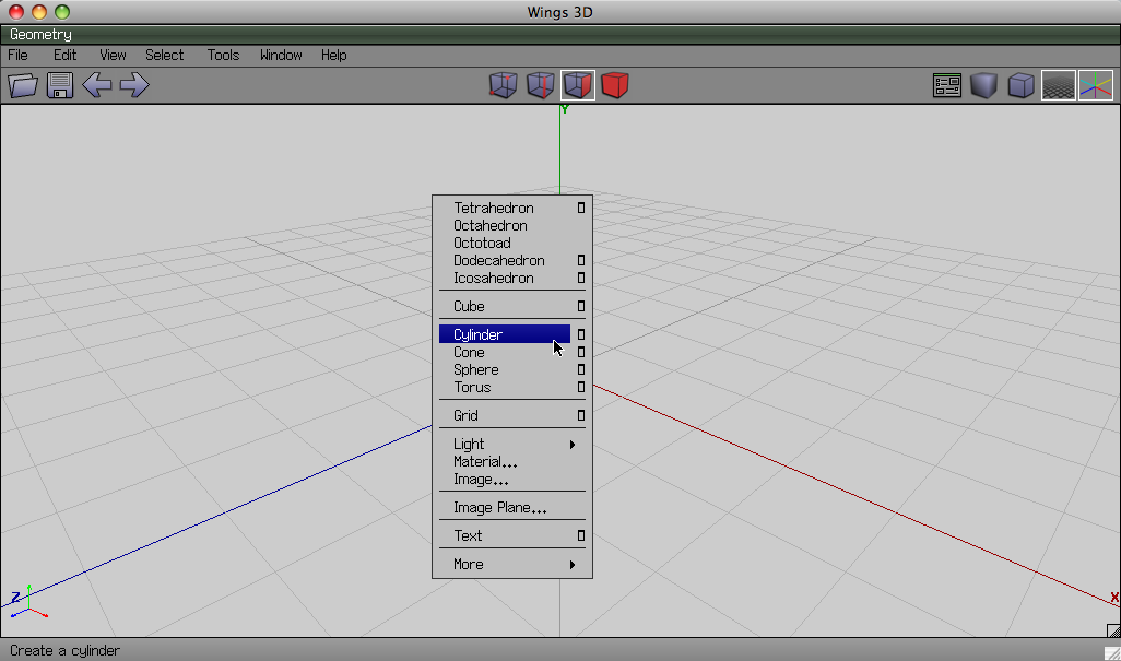
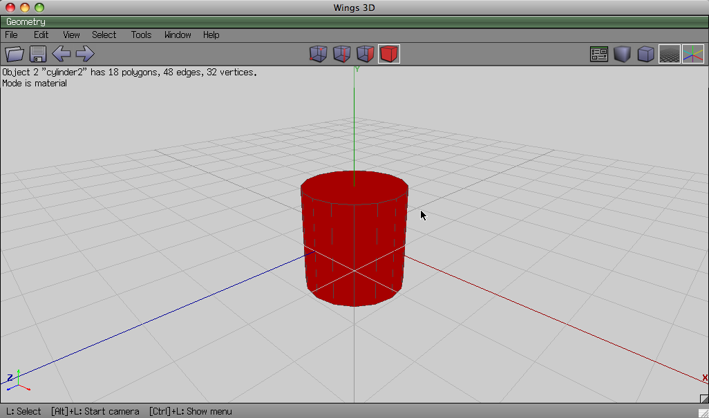
- Right click anywhere and choose Cylinder from the drop-down menu. This will spawn a default 16-sided cylinder, to spawn a customized cylinder press the little box on the same line instead. We will now change the proportions of the cylinder to our liking.
- Go into object mode (B) and select the cylinder.
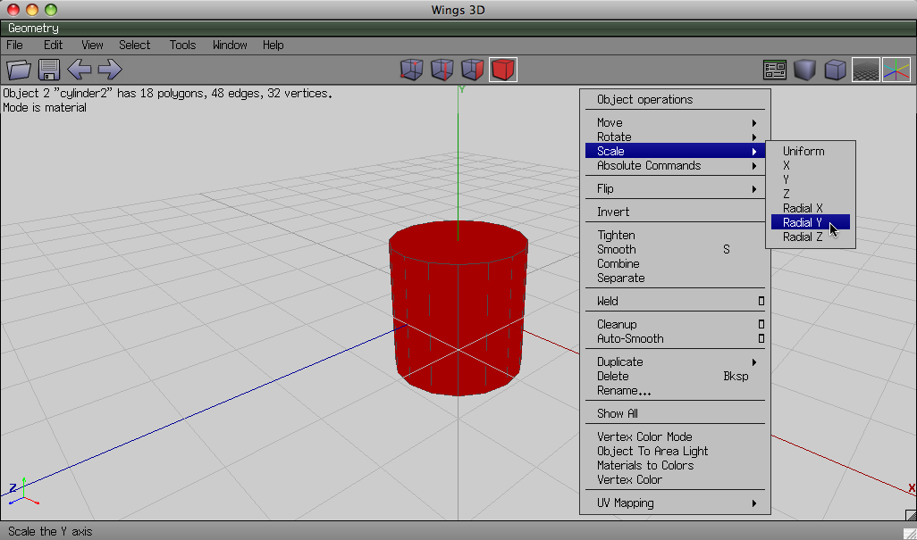
- Right click anywhere to open the drop-down menu and select Scale -> Radial Y.
- Now drag the mouse side to side to change the width of the cylinder. Click once it is scaled to your liking to accept, or press tab to manually input a value.
- For the purpose of this tutorial our cylinder model is now finished.
Now we need to generate a UV map for the object so we can texture it.
UV Mapping the model
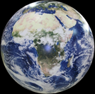
When you want to apply a texture to a 3D model, you might run into some problems. The best way we know how to deal with textures is as a 2D image, but how do we take a 3D model, and make a 2D image out of it? Well let's imagine that we have an orange painted like a globe like this:
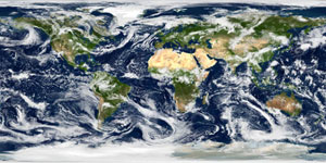
And we want to make its surface flat kinda like this:
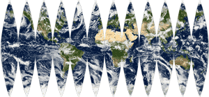
The solution is we peel away the surface, cutting it in a certain way so that it lies flat:
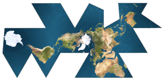
Please note that there are many ways of doing this, but some work better than others. For example one of the more accurate ways of doing this with the earth is what's known as Fuller's Projection:
This is what we have to do with our cylinder: We have to cut it up so that we can lay it flat on a 2D plane.
Each vertex of the model, which already has a 3D coordinate of (X,Y,Z) will now also have a 2D coordinate on this special plane, so that we know how to fit the texture onto our object. This 2D coordinate is defined as (U,V), which is why this is called UV mapping. This is a simplified way of describing UV mapping, but for this tutorial it will do.
Note: there are other methods for applying textures to models, but this guide only covers UV mapping.
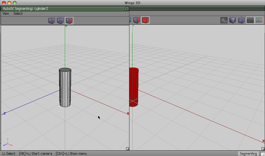
1. Select the entire object, and at the bottom of the drop-down menu choose UV Mapping -> Direct. A new window with the object will pop up with a title of AutoUV Segmenting: and the name of your object:
Now we have to Divide the object into different shapes so that it can unfold it properly, just like in the globe example. This can be done Automatically or Manually. For the sake of practice let's do it by hand: You can separate different pieces either by marking which edges to cut, by coloring the faces that should go together, or both.
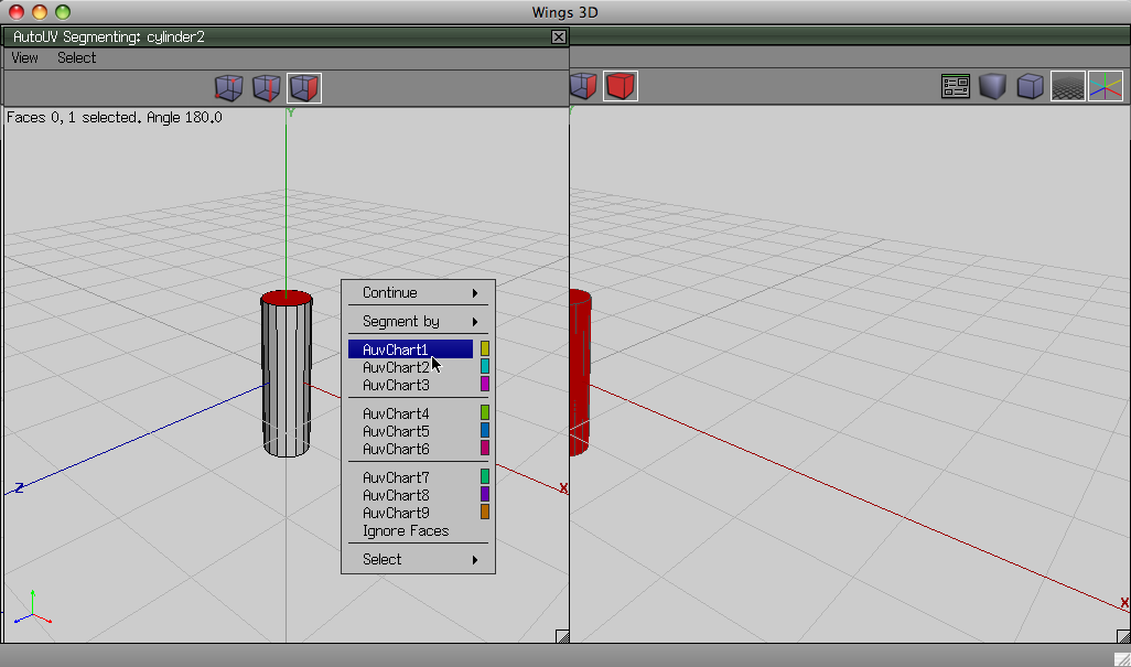
2. In face mode (F) select the top Face and press 'i' (select similar) so both the top and bottom are selected. Choose one of the nine colors Labeled AuvChart1-9 from the drop-down menu. Doing so will mark these faces as being separate from the rest of the model.
3. Clear your selection with space, and select one of the vertical side pieces. Select the rest by selecting similar (i), then mark these with a different color.
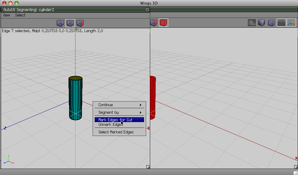
4. Because the cylindrical part of the model is still in a loop we need to mark a cut. In Edge mode (E) select of the vertical edges and choose 'mark edges for cut' from the drop down menu.
5. The marking of your model is now complete, and it is ready to be unfolded. Choose Continue->Unfolding from the drop down menu
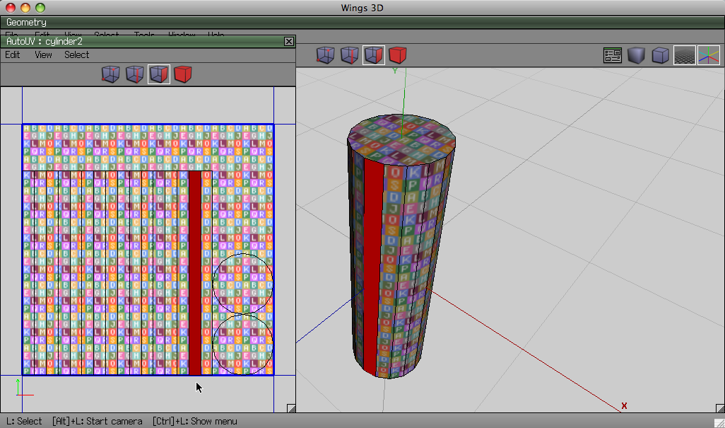
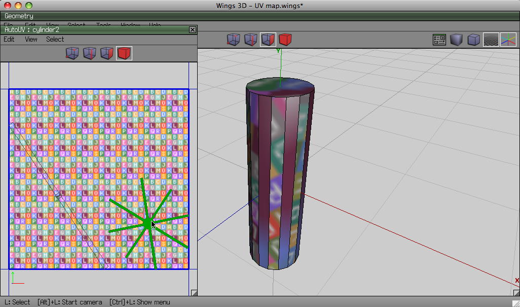
6. A window showing the unfolded model will open up. This is the UV map. To show what part of the UV map belongs to what part of the model, there is a colorful grid and letter pattern that you can also see on your model. When you Select a face you see it on both the model and the UV map.
You can also scale and move parts of the model around on the UV map, and the changes will be apparent on the model. Making a face take up more of the UV map will make give it a denser more detailed texture. This is often used to make important features of a model more detailed, like the hands and dace of a character.
If for whatever reason you don't like how the unfolding ended up you can select your object, and in the drop down menu Choose UV Mapping-> Force Segment (delete previous) to start from a clean slate.
It's important to note that there can be many different ways of cutting an object and the resulting UV maps can look very different.
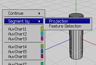
There are two automated methods, Projection and Feature Detection:
Depending on your model one might be better than the other, sometimes they both suck and you have to do it manually, and sometimes if your model is simple like this one they will both give you the same result.
If you cut the object in weird ways it will end up unfolding weirdly, like this for example:
Once again, the best way to understand how this works is to experiment and try out the various features.
Although there are many different ways of mapping any Model, as a rule you want its faces to use the UV space as efficiently as possible, because any texture that isn't under the mapped Faces will not be seen anywhere when the texture is applied.
There are entire programs devoted simply to finding the best way to generate the UV map for any given model, and the tools wings3D provides are much more basic. However they are sufficient for a simple object like this. With practice you can even manage more complex ones.
Now that We've Finished UV mapping let's generate the texture for the model. Rest assured, the hardest part is done.
Generating a texture from the UV Data
We have our lovely UV map, and now we need to generate a texture we can then edit.
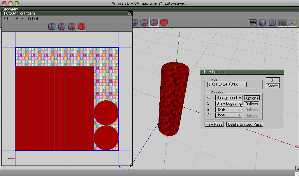
1. With the UV map Window still open, choose 'Create Texture' from the drop-down menu. A small window will pop up:
Choose a size depending on how big the object will end up being, and how detailed you want it to be. The larger the image, the more detailed the texture will look on the model. It wouldn't make sense to have a super-high detailed texture for a fork, and you wouldn't want a low quality texture for a skyscraper either. For this object 512x512 will work just fine.
2. Because we want to edit this texture manually later we need to know where on the texture the edges of the object are, so we know where on the object we are drawing. Set the first as 'Background' and the second as 'Draw Edges' so the edges appear on the texture. Press OK.
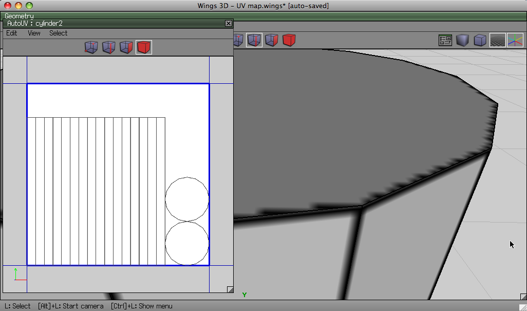
3. It might seem like the UV map disappeared, but don't fear, the texture was created and is now applied to the object. You simply cannot see it well because it is white with black lines that are right under the wire-frame. You can tell when you zoom in really closely:
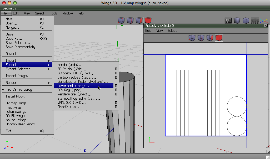
4. Export the model by going into File -> Export -> Wavefront (.obj)
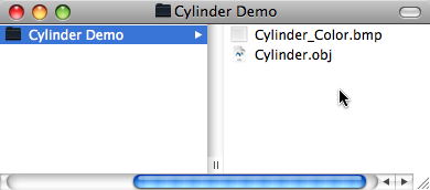
Then make a new folder in a location of your choosing and save it as whatever title you like. It will save a .obj and a .mtl file. Delete the .mtl file. It has to do with materials that we don't need.
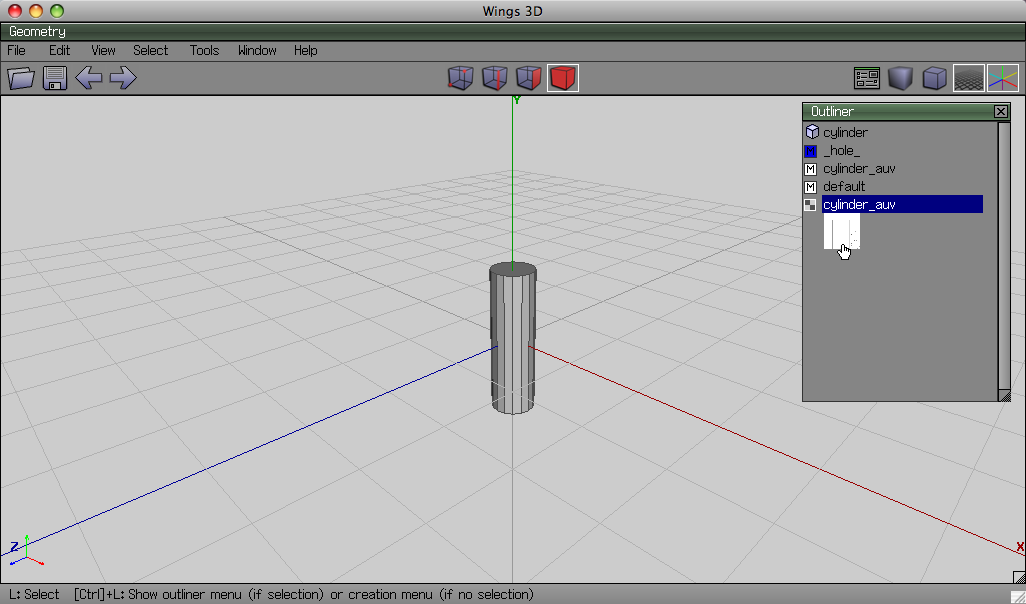
5. Sometimes the texture is saved along with the object, but sometimes it isn't. If there is no texture file in the folder you exported to, go into Window->Outliner, and locate the texture:
Right click it, Choose export and save it in the same folder as the obj, name it whatever you want, preferably the name of your object plus _Color. For example:
You are now done with Wings3D!
Editing the texture
Now it's time to get creative!
- Load the Texture file into whichever image editing program of your choice
- Create your actual texture now however you wish. It helps to keep your 'Template' in a separate layer than the texture you want to be on your object.
Here is one way of doing it in photoshop, that allows you to keep the Template's lines above your texture for reference:
- Double click the layer name and accept the pop up prompt to unlock it.
- Rename the layer "template".
- Create two layers bellow it, the lower one called background, the upper one called texture.
- Fill The background layer with white and lock it.
Image_2.png (19.76 KiB) Viewed 579 times
- Select the Template layer, which is above all the other layers, and set its layer mode to multiply.
Image_3.png (37.59 KiB) Viewed 580 times
This will make the white in it transparent, and the black remain as an overlay. you can use it as a guide. lock it as well.
- Draw in the texture layer to your heart's content.
I just used some stock photography I found online. The area with the red text is wasted space that could have been better managed when I made the UV map. It will not appear on the final Model, but will take up space in memory none-the-less.
Here is my finished texture: Image_5.png (326.33 KiB) Viewed 578 times
Once done, make sure to save the image -without- the Template, unless you want it as part of the final Texture. Don't worry too much about what format you save it as. Thanks to the built in image converter almost any file type will work in the engine. I personally would advise you to use .tga or .png.
Changing the Reflectivity of the texture
If you were to use this texture as it is, the resulting object would look very shiny. That is because Phoenix will set the reflectivity, or inherent 'shininess' of an object depending on the transparency, or alpha value of the texture.
If you want your object to look more matte you need to add transparency to your texture. There are several ways to do this:
The Simple way:
- This method will make the whole texture less shiny:
- Look in the Layer window and change the Opacity of the Layer that contains your texture.
Reflect_1.png (15.61 KiB) Viewed 576 times
- You're done. Save the texture, but make sure that the format you save it as supports Transparency. .tga and .png both do.
The Advanced way:
- This method will allow you to change the shininess of different parts of the texture.
- Find the Channel window. You should see 3 channels, Red, Green and Blue (RGB is simply the sum of all 3):
Reflect_2.png (15.26 KiB) Viewed 575 times
- Add a new Channel (the icon next to the trashcan) By default this is an Alpha Channel.
Reflect_3.png (15.46 KiB) Viewed 570 times
- Like all channels it is black and white. Black is Transparent, and will make the object matte, and White is Opaque, and will make the object reflective.
- If you show the rest of the channels while the alpha channel is visible the parts that are hidden will appear red by default:
- When Finished save the file, but make sure to save it as .tga The alpha layer will -not- be saved if you choose .png
Making a normal map for the texture
This tutorial does not yet include Instructions for making a normal map. Until someone writes it up, just use the following blank normal map: blanknormal.png (5.36 KiB) Viewed 566 times
Setting up the folders
Phoenix, Overgrowth's engine uses XML files to tell it where an object's files are located. These XML files are by default located in Data/Objects. For example the Rock1a.xml file:
<?xml version="1.0" ?>
<Object>
   <Model>Data/Models/Environments/Rocks/Rock1a.obj</Model>
   <ColorMap>Data/Textures/Environments/Rocks/Rock1_Color.tga</ColorMap>
   <NormalMap>Data/Textures/Environments/Rocks/Rock1_NormalOS.tga</NormalMap>
   <ShaderPath>Data/GLSL/cubemapobj</ShaderPath>
   <ShaderName>normalmap</ShaderName>
</Object>
The way the file works is self explanatory. The tags indicate what the provided file path points to. As you can see all the file paths have Data as their root. Because of this you'll want your files to be inside the Data folder.
For mac users right click the Alpha, click 'Show Package Contents', Contents->Data. For easy access then drag it into your Sidebar: Folder_1.png (46.58 KiB) Viewed 563 times
Until the team implements a more elegant solution I suggest that in the Data folder you make a folder called Custom and keep all your files in there. I chose to imitate the file structure in Custom that the Data folder uses by default: PICTURE
However you can save it any way you choose. If you want to share your Objects with others it is be best to keep all the files in one Folder inside Data/Custom. ultimately in the engine it doesn't make a difference, as long as the XML file is defined correctly
Making the XML file
Now that everything is in the right place you can make the xml Object file.
- Copy any .xml file from the Objects Folder, paste it into your custom folder and rename it as whatever you want. make sure to keep the extension ".xml"
- Open the XML file with a text editor and change the paths to match that of your file.
Here's mine:
<?xml version="1.0" ?>
<Object>
  <Model>Data/Custom/Models/Demo/Cylinder.obj</Model>
  <ColorMap>Data/Custom/Textures/Demo/Cylinder_Color.png</ColorMap>
  <NormalMap>Data/Custom/Textures/Demo/Blank_Normal.png</NormalMap>
  <ShaderPath>Data/GLSL/cubemap</ShaderPath>
  <ShaderName>cubemap</ShaderName>
</Object>
</code>
I don't quite know how the shaders work, but I tested each out and listed them here. Cubemap will work best for most objects.
Testing the object in the engine
Now the moment you've been waiting for:
- Start up the Latest Alpha
- Click the first Button in the toolbar
- Find your .xml object file and click Open
- Pray that you've done everything right and click on the terrain
- Breathe a sigh of relief as your object appears:
The above Object uses a texture without transparency and so looks shiny.
This Object uses a texture with transparency and so has matte areas:
If you get an error message saying that a file cannot be found make sure that the file-paths in the XML Object file are correct.
Here is the final Custom Folder which I made for this tutorial. It contains two objects: one with changed reflectivity, and one without.
FILE
unzip it, make sure the resulting folder is called 'Custom" (otherwise the xml file paths would be incorrect) and place it in the Data folder.
(Notice that I actually did a bad job with the UV mapping, because I chose to automate it and not do it manually, and the texture is not a continuous band, but broken up into 4 parts.)
Conclusion
I really hope that this Guide will be helpful to you. A-lot of thought and effort went into it, plus at least a good 5+ hours of work
One thing I cannot stress enough is that this guide is by no means perfect, and there are likely better ways of doing this.
My challenge to you is to not just use this guide, but expand on it: Try texturing a sphere, a rock, a Tree, never stop experimenting. Apply what you've learned here and use it to help you make some great content for this game.
If you have any questions or problems when trying to recreate what is illustrated here, please feel free to ask the friendly people in our IRC channel.
Other Resources
LINKS
